Difference between revisions of "Graphics"
(Created page with "=== Outputting in mode 13h (320x200) === ==== Basic pixel output ==== The videomemory for mode 13h is located at segment 0xA000, so you need to assign this value to a segmen...") |
|||
| (5 intermediate revisions by the same user not shown) | |||
| Line 7: | Line 7: | ||
<syntaxhighlight lang="nasm">mov al,0x13 | <syntaxhighlight lang="nasm">mov al,0x13 | ||
int 0x10 ; AH = 0 means : set video mode to AL = 0x13 (320 x 200 pixels in 256 colors) | int 0x10 ; AH = 0 means : set video mode to AL = 0x13 (320 x 200 pixels in 256 colors) | ||
| + | |||
push 0xA000 ; put value on the stack | push 0xA000 ; put value on the stack | ||
pop es ; pop the top stack value into segment register ES</syntaxhighlight> | pop es ; pop the top stack value into segment register ES</syntaxhighlight> | ||
| + | |||
| + | To initialize the ES segment, you can also do : | ||
| + | <syntaxhighlight lang="nasm">mov ah,0xA0 | ||
| + | mov es,ax</syntaxhighlight> | ||
| + | both variations occupy 4 bytes, but the latter is executable on processor architectures where ''push <word>'' is not available. | ||
You're free to use any of the segment register / opcode combinations to write to the screen | You're free to use any of the segment register / opcode combinations to write to the screen | ||
| Line 32: | Line 38: | ||
| − | + | ==== LES segment initialisation trick ==== | |
| − | <syntaxhighlight lang="nasm"> | + | <syntaxhighlight lang="nasm">les bx,[bx]</syntaxhighlight> |
| − | + | to save two bytes. This works because BX is 0x0000 at start and thus, accesses the region ''before'' our code, which is called [https://en.wikipedia.org/wiki/Program_Segment_Prefix Program Segment Prefix]. The two bytes that are put into the segment register ES are bytes 2 and 3 = ''"Segment of the first byte beyond the memory allocated to the program"'' which is usually 0x9FFF. That is just off by one to our desired 0xA000. Unfortunately that means a 16 pixel offset, so if screen alignment means something to you, you can't use this optimization. Also, said two bytes are not always 0x9FFF; for example, if resident programs are above the ''"memory allocated to the program"'' (FreeDos), their content is overwritten if we take their base as our video memory base. | |
| − | |||
| − | |||
| − | |||
| − | |||
| − | ==== | + | === Using the Rrrola constant === |
| + | Using the Rrrola constant is a nice shorthand way to quickly get a pair of X,Y coordinated into registers DL and DH. | ||
| + | As a bonus both the X and Y coordinates are within 0..255 byte range, which makes them easy to work with. | ||
| + | Here is an example of how to use it: | ||
| − | + | <syntaxhighlight lang="nasm"> | |
| − | <syntaxhighlight lang="nasm">push 0xa000 | + | mov al,0x13 |
| − | pop es | + | int 0x10 |
| − | + | push 0xa000 | |
| − | + | pop es | |
| − | + | frameloop: | |
| + | mov ax,0xCCCD ; rrrola constant | ||
| + | mul di | ||
| + | mov al,dl ; get screen position (256 x 256) into DH (y) and DL (x) | ||
| + | xor al,dh ; the famous XOR pattern | ||
| + | and al,15 ; 16 shades | ||
| + | add al,16 ; add 16 for greyscale | ||
| + | stosb ; store pixel | ||
| + | jmp frameloop | ||
| + | </syntaxhighlight> | ||
| − | + | === Use BIOS for pixel plotting === | |
| + | We can use an alternative way of putting pixels to the screen, subfunction AH = 0x0C of int 0x10. Also, instead of constructing row and column from the screen pointer, we can use some interesting properties of the screenwidth regarding logical operations. This results in the following 16 byte program: | ||
<syntaxhighlight lang="nasm">cwd ; "clear" DX for perfect alignment | <syntaxhighlight lang="nasm">cwd ; "clear" DX for perfect alignment | ||
Latest revision as of 14:36, 8 April 2024
Contents
Outputting in mode 13h (320x200)
Basic pixel output
The videomemory for mode 13h is located at segment 0xA000, so you need to assign this value to a segment register. Also, after the start of your program you are normally still in textmode, so you need to switch to the videomode. The following snippet does both:
mov al,0x13
int 0x10     ; AH = 0 means : set video mode to AL = 0x13 (320 x 200 pixels in 256 colors)

push 0xA000  ; put value on the stack
pop es       ; pop the top stack value into segment register ES
To initialize the ES segment, you can also do :
mov ah,0xA0
mov es,ax
both variations occupy 4 bytes, but the latter is executable on processor architectures where push <word> is not available.
You're free to use any of the segment register / opcode combinations to write to the screen
-
ES(stosb) -
DS(mov) -
SS(push)
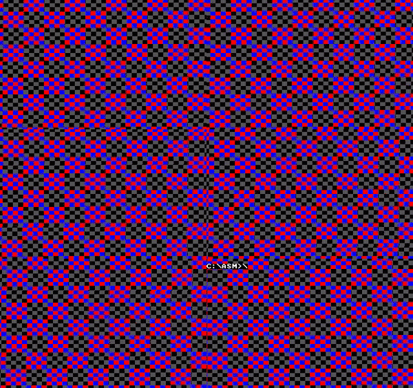
Let's add some code that actually draws something on the screen, the following program occupies 23 bytes and draws a fullscreen XOR texture
mov al,0x13
int 0x10
push 0xa000
pop es
X: cwd			; "clear" DX (if AH < 0x7F)
mov ax,di		; get screen position into AX
mov bx,320		; get screen width into BX
div bx			; divide, to get row and column
xor ax,dx		; the famous XOR pattern
and al,32+8		; a more interesting variation of it
stosb			; finally, draw to the screen
jmp short X		; rinse and repeat
LES segment initialisation trick
les bx,[bx]
to save two bytes. This works because BX is 0x0000 at start and thus, accesses the region before our code, which is called Program Segment Prefix. The two bytes that are put into the segment register ES are bytes 2 and 3 = "Segment of the first byte beyond the memory allocated to the program" which is usually 0x9FFF. That is just off by one to our desired 0xA000. Unfortunately that means a 16 pixel offset, so if screen alignment means something to you, you can't use this optimization. Also, said two bytes are not always 0x9FFF; for example, if resident programs are above the "memory allocated to the program" (FreeDos), their content is overwritten if we take their base as our video memory base.
Using the Rrrola constant
Using the Rrrola constant is a nice shorthand way to quickly get a pair of X,Y coordinated into registers DL and DH. As a bonus both the X and Y coordinates are within 0..255 byte range, which makes them easy to work with. Here is an example of how to use it:
mov al,0x13
int 0x10
push 0xa000
pop es
frameloop:
mov ax,0xCCCD   ; rrrola constant
mul di
mov al,dl        ; get screen position (256 x 256) into DH (y) and DL (x)
xor al,dh        ; the famous XOR pattern
and al,15        ; 16 shades
add al,16        ; add 16 for greyscale
stosb            ; store pixel
jmp frameloop
Use BIOS for pixel plotting
We can use an alternative way of putting pixels to the screen, subfunction AH = 0x0C of int 0x10. Also, instead of constructing row and column from the screen pointer, we can use some interesting properties of the screenwidth regarding logical operations. This results in the following 16 byte program:
cwd             ; "clear" DX for perfect alignment
mov al,0x13
X: int 0x10		; set video mode AND draw pixel
inc cx			; increment column
mov ax,cx		; get column in AH
xor al,ah		; the famous XOR pattern
mov ah,0x0C		; set subfunction "set pixel" for int 0x10
and al,32+8		; a more interesting variation of it
jmp short X		; rinse and repeat
The first optimization is the double usage of the same "int 0x10" as setting the videomode and drawing the pixel. The subfunction AH = 0x0C expects row and column in DX and CX. Since the screenwidth is 320, which is 5 * 64, we can ignore the row and just works with the column, if we use logical operations and just use bit 0-6 of the result. The subfunction AH = 0x0C allows for unbounded column values in CX (up to 65535) and correctly "wraps" it internally without an error.
The major drawback of the "subfunction AH = 0x0C" approach is performance loss. While DosBox and many emulators perform just fine, real hardware will draw much much slower based on the Video BIOS.
Basic animation and user interaction
Now let's add the convenient check for the ESC key and also add a simple animation. The DI register is used as frame counter and incremented after the pixel counter CX ran through all 65536 values via LOOP. This frame counter is then added to the column. The resulting program is now 25 bytes in size :
cwd             	; "clear" DX for perfect alignment
mov 	al,0x13
X: 		int 0x10	; set video mode AND draw pixel
mov 	ax,cx		; get column in AH
add		ax,di		; offset by framecounter
xor 	al,ah		; the famous XOR pattern
and 	al,32+8		; a more interesting variation of it
mov 	ah,0x0C		; set subfunction "set pixel" for int 0x10
loop 	X			; loop 65536 times
inc 	di			; increment framecounter
in 		al,0x60		; check keyboard ...
dec 	al			; ... for ESC
jnz 	X			; rinse and repeat
ret					; quit program
( ↑ This example is the blueprint in the FPU Basics Section.)
Using Custom Colors
Shades of Hue within the Default VGA palette
You might have noticed there is a bit of structure to the default VGA Palette, which you can exploit for some interesting results. Looking at the pallete there is a rainbow of different hue values that start at index 32 that are repeated in a slightly different luma seperated by 72 indices. If you are okay with limiting the amount of shades you need, you can get a small colorramp for all kinds of hue values by simply calculating your color-index like this:
color=((shade%3)*72)+32+huevalue
For an example of how this looks for all kinds of hue values, see Popcast by Hellmood/Desire.
Setting a Custom Palette
Sometimes, when the Default VGA Palette doesn't quite match the look you are looking for, it can be useful to set your own palette using the VGA registers, the basic setup loop looks like this:
palloop:
mov ax,cx
mov dx,0x3c8
out dx,al    ; select palette color
inc dx
out dx,al    ; write red value (0..63)
out dx,al    ; write green value (0..63)
out dx,al    ; write blue value (0..63)
loop palloop
The above code sets a simple grayscale palette, assumes CX Register to be at 0) and is compatible with all DOS platforms.
In some cases you can ommit the mov dx,0x3c8, out dx,al, inc dx and directly access the data register by just using mov dx,0x3c9 instead.
To get more interesting colors than just grayscale, you can alter the value of the AL register in between setting the red, green and blue values. For example by shifting, adding, substracting or performing logical operations. Just get creative and check if the result is sufficient for your usecase.
TomCat will show the most common color palettes grouped by functionality. Check his article: Colors (in tiny intros)

